14.8.15

Double Bazooka NVIS Antenna Calculator


The measurements below are for building a Double Bazooka Near Vertical Incident Skywave (NVIS) Antenna. The End Wire Size can range from 16 AWG to 12 AWG. The larger the wire, the wider the bandwidth. 300 Ohm Twin Lead with the ends shorted is an option for even greater bandwidth.
The antenna is constructed from a single length of 50 or 75 Ohm coax with a coaxial feed point in the center. The span is opened in the middle to expose the braid from each half. The center conductor and dielectric is not disturbed and the two separated braids are then fed with the Coax Feedline. Each end of the coaxial span has the braid and center conductor shorted and connected to the end wires.
The antenna as designed is a broad band antenna with the coaxial cable's capacitive reactance changing to compensate for changes in inductive reactance across the band of operation. This helps to provide acceptable matches on frequencies other than what the antenna was specifically designed for. The antenna as fed matches reasonably well into a 50 Ohm Coax Cable Feedline and an antenna tuner.
A Ground Reflector can be added to enhance NVIS Propagation at frequencies below 10 MHz where NVIS Propagation is usable. The Ground Reflector can be a single conductor or several in parallel spaced a few feet apart. Hardware cloth or "Poultry Screening" is an option too. Several antenna / reflector elevation options are shown that enhance the NVIS vertical antenna pattern and propagation.


Please note: The calculations are approximate, so some final end wire length adjustment may be necessary. Dimensions will change slightly due to antenna height and ground conductivity variations...and Keep The Antenna Away From Power Lines. They are good at turning you into "The Squirrel in the Substation".

Please note: NVIS Propagation is only useful at frequencies below 10 MHz.


Double Bazooka AntennaNVIS Antenna HeightRef Dipole


 End Wire Length Ft (B)Coax Element Length (C)Coaxial Element Center (D)Total Length Ft (E)0.1 Wave1/8 Wave1/20 WaveReflector Length1/2 Wave Ft
160 Meters


1.837.50180.5690.28255.5652.0065.0026.00268.33260.00
1.935.53171.0585.53242.1149.2661.5824.63254.21246.32
233.75162.5081.25230.0046.8058.5023.40241.50234.00
80 Meters


3.519.2992.8646.43131.4326.7433.4313.37138.00133.71
3.618.7590.2845.14127.7826.0032.5013.00134.17130.00
3.718.2487.8443.92124.3225.3031.6212.65130.54126.49
3.817.7685.5342.76121.0524.6330.7912.32127.11123.16
3.917.3183.3341.67117.9524.0030.0012.00123.85120.00
416.8881.2540.63115.0023.4029.2511.70120.75117.00
60 Meters


5.330512.6660.9730.4886.3017.5621.958.7892.1987.80Ch1
5.346512.6360.7930.3986.0417.5121.888.7591.9187.53Ch2
5.366512.5860.5630.2885.7217.4421.808.7291.5787.21Ch3
5.371512.5760.5030.2585.6417.4321.788.7191.4887.13Ch4
5.403512.4960.1530.0785.1317.3221.658.6690.9486.61Ch5
40 Meters


79.6446.4323.2165.7113.3716.716.6969.0066.86
7.19.5145.7722.8964.7913.1816.486.5968.0365.92
7.159.4445.4522.7364.3413.0916.366.5567.5565.45
7.29.3845.1422.5763.8913.0016.256.5067.0865.00
7.39.2544.5222.2663.0112.8216.036.4166.1664.11
30 Meters


10.16.6832.1816.0945.549.2711.584.6347.8246.34
10.156.6532.0216.0145.329.2211.534.6147.5946.11
20 Meters


144.8223.2111.6132.866.698.363.3434.5033.43
14.14.7923.0511.5232.626.648.303.3234.2633.19
14.24.7522.8911.4432.396.598.243.3034.0132.96
14.224.7522.8611.4332.356.588.233.2933.9732.91
14.34.7222.7311.3632.176.558.183.2733.7832.73
14.314.7222.7111.3532.146.548.173.2733.7532.70
17 Meters


18.073.7417.998.9925.465.186.482.5926.7325.90
18.133.7217.938.9625.375.166.452.5826.6425.81
15 Meters


213.2115.487.7421.904.465.572.2323.0022.29
21.13.2015.407.7021.804.445.552.2222.8922.18
21.23.1815.337.6721.704.425.522.2122.7822.08
21.33.1715.267.6321.604.395.492.2022.6821.97
12 Meters


24.892.7113.066.5318.483.764.701.8819.4118.80
24.952.7113.036.5118.443.754.691.8819.3618.76
10 Meters


282.4111.615.8016.433.344.181.6717.2516.71
28.52.3711.405.7016.143.284.111.6416.9516.42
292.3311.215.6015.863.234.031.6116.6616.14
29.52.2911.025.5115.593.173.971.5916.3715.86

13.8.15

Antenna Tunner by Radio Bengkel

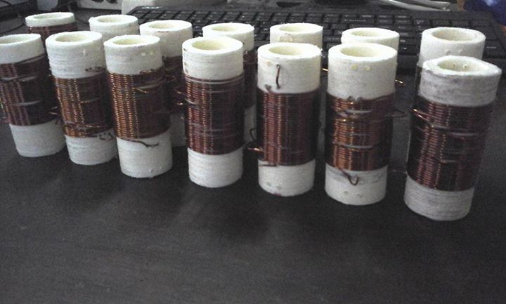
TEST COIL TUNNER : 20.60 uH - 13.80 uh - 6.34 uh - 5.59 uh - 5.79 uh - 2.51 uh - 4.12 uH


7MHz helical antenna φ15mm Preparation Example

7MHz helical antenna φ15mm Preparation Example


fabrication example 7MHz helical antenna using the glass rod of φ15mm we will continue to introduce along with the parts description. This antenna is can be produced by a helical handy size of around 1m ~ 1.2m.


(Upper left) φ3mm element tip mounting bracket \ 100 
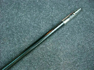
(center) Ï†3 × 500mm stainless element \ 600 element is used to cut, if necessary at the time of the adjustment. Element tip mounting bracket, then fixed by press fitting (hammering). Since the removal of the post-mounting is not possible, install it after the last adjustment is complete. Lower right is the attached image.


φ9-φ3mm element adjustment bracket \ 500 is a bracket to attach to the glass rod top. The inner diameter of the large hole φ9mm, has become a small inner diameter of the hole is φ3mm, φ3mm side, can be fixed with screws from the side.


φ15.5-φ8.5 × 1180mm glass rod of the image I have sold out. Rod that is handled currently is glass rod of φ16-φ9 × 1300mm.


 Ï†15mm insulation base connector and the center pin of the M-type connector, is a type of sleeve portion of the above is conducting from the black insulator


It has been applied threaded to help you add a matching coil and condenser in with later in this antenna.


φ1.0mmPEW wire in this antenna I've used about 26 meters


Heat shrinkable tube of Mitsubishi Plastics sebum is the tube (R). This time, we used two because in it is not possible to cover the whole single (size) (size). Ori径29.5mm φ18mm → φ12mm  (1m) Ori径23mm φ14mm → φ9mm (1m)


The glass rod, attach the element mounting bracket was cut is the thickness at the position of a little less than φ9mm. The mounting I use an epoxy resin based adhesive. If you want to use as long as possible with a glass rod, it was cut at the position of the little bracket loose position, and attach it plenty with the adhesive. Conversely, it was cut in a little bracket tight position if you want to finish as short as possible, in some cases you can attach the bracket by adjusting the thickness of a sand paper.


Similarly, a glass rod, the thickness Attach the insulation base connector is cut at the position of about φ15mm.


By soldering the wires to the adjustment bracket, we will wound the wire.Winding start is wound a few turns rough, then wound tightly about 21m minutes.


We will continue to the rest of the wire to the interval winding. You can clean interval winding When involving the wire of the same thickness together.


As last 50cm ~ 1m is in the rough winding, and then soldered to the insulating connector. Here once, leave the provisional adjusted mounting elements. Leave close to the element length of preference to cut the wire as needed. As Notes for adjustment, when it was condensed adjustment elements, beyond the position of the position or B in A SWR value is deteriorated or the resonant frequency may deviate significantly. In such a case, by cutting the element at the position of A, ensure that fit the position of the right image when attaching. Provisional adjustment covered with a heat-shrinkable tubing When you have finished. First of all, it is covered with a heat-shrinkable tubing from thicker (lower).


Then we will put the thinner the (person above). When cover thinner and can be shorten by superimposing more than 1 ~ 2cm in heat-shrinkable tubing which is placed over the thicker.


Finally, it is complete with the up and down is not final adjustment the adjustment element. In this case, the adjustment for the element we were able to adjust the position of about 17cm. Add the matching coil and a capacitor, if necessary.


10.8.15

antenna 11.400 Mhz


1. Lubangi Pangkal / bagian bawah Fiber standard 130cm.
2. Lubangi bagian atas supaya tembus.
3. masukkan kawat tenbaga 1mm.
4.Masukkan Konektor.
5.Gunakan Lem DEVCON Plastic steel.
6 Lem Konektor dan tunggu 30 menit.
7. Gulungkan email 0,55mm, 45cm renggang, panjang email 17~18meter.
8. Gulung rapat hingga ujung fiber.
9. Kepadatan gulungan harus dijaga.
10. Lilit hingga ujung Fiber.
11. Tampak Konektor dan solderan email untuk tuning panjang pendek email.
12. Saatnya tuning di mobil.


9.7.15

Komponen-komponen kritis dalam BITX


Komponen-komponen kritis dalam BITX

Tiga bulan lalu saya merangkai BITX (terima kasih Om Suhardi Iskandar). 
Keberhasilan dalam membuat transceiver adalah PEMILIHAN KOMPONEN DAN DISTRIBUSI GAIN YANG TEPAT. Skema saya ambil dari blognya Om Yoke Kurnia (http://2.bp.blogspot.com/-yN8YsLjbbbA/TvqYWs1vrcI/AAAAAAAAAJk/s-Z6VuiKsww/s1600/bitx20.ver3.gif)


Ada beberapa komponen2 kritis untuk "tune-up" yang akan saya share disini.

1. Transistor Q1 dan Q2 sebaiknya menggunakan 2SC2570. TR ini cukup low noise. Jika ingin diganti, bisa menggunakan 2SC2053, MPSH10, MPSA18. Dalam beberapa kasus suara krotokan dan noise yang kuat muncul dari bagian ini. Tahap ini fungsinya untuk "mengkompensasi" loss yang timbul di BPF dan diode mixer. Jika BPF dan mixer punya loss sekitar -13db, maka penguatan total dibagian ini sebaiknya juga disekitar itu. Rata2 penguatan tahap ini sekitar +12db, atau +24db (RF amp + post mixer amp). Penguatan post-mixer sebaiknya tidak lebih dari 10db, jika lebih, bisa mengakibatkan kristal filter "ringing" atau berderik, dan bisa lebih parah lagi, tuuuuut. Ini ciri khas kristal filter yang punya impedansi rendah. Bagaimana caranya mengurangi penguatan? perbesar nilai R1 dan R2 menjadi 15-22 ohm.

2. T1 dan T1A sebaiknya dimodifikasi jumlah gulungannya. Karakter dari trafo broadband (material 43, balun tivi) digulung berapa saja, impedansi-nya akan mengikuti besarnya impedansi beban atau terminasi. Tetapi nilai XL-nya juga semakijn tinggi, yang akan berakibat pada sisi sensitifitas. Dari eksperiment disini, saya hanya perlu 4 lilitan trifilar di T1A dan 4 lilitan bifilar + 8 lilitan (primer) di T1.

3. Kapasitor Cx sebaiknya diganti dengan 100pf agar matched

4. R3 gunakan 220 ohm untuk CF 8Mhz, 150 ohm untuk CF 10Mhz, 120 Ohm untuk 12Mhz.

5. R5 sebaiknya di perbesar menjadi 15-22 ohm. Ini biang keladi carrier sudah muncul walaupun belum dimodulir.

6. Cy sebaiknya ganti dengan 22nF-33nF, sekaligus sebagai LPF sederhana. Jika memungkinkan tambahkan kopling L minimal 100uH sebelum masuk preamp.

7. Karena output impedansi product detector rendah (50-100 ohm), sebaiknya menggunakan low impedance preamp. Skemanya banyak di google, atau bisa menggunakan http://wiringcircuitdiagram.wiringdiagramcircuit.com/tag/low-impedance-input-pre-amp/

Selamat mencoba.

6.7.15

BALUN bukan BALON

Dari sahabat...YC3CB
BALUN, BALance to UNbalance
Saya kali ini ingin berbagi pengetahuan dan pengalaman mengenai Balun. Tulisan ini tidak bermaksud untuk berpolemik apakah antena itu memerlukan balun atau tidak, tetapi berdasarkan referensi yang saya baca dan juga berdasarkan pengalaman ternyata ada beberapa keuntungan yang kita dapat kalau antena kita pasang balun, diantaranya :
a. Performance antena dapat ditingkatkan.
b. Mengurangi TVI ( Interferensi ke televisi )
c. Mengurangi unbalance current.
d. Mengurangi radiasi yang tidak diinginkan
e. Memperbaiki pola radiasi pancaran.
Balun selain berguna untuk menghubungkan antena yang Balance dengan feeder line (coaxial cable) yang Unbalance juga sekaligus berguna untuk penyesuai impedansi antara antena, feeder line, dan radio tranceiver. Ada beberapa macam atau jenis balun diantaranya, Balun 1 : 1, Balun 1 : 4, Balun 1 : 6, Balun 1 : 9, Balun 1 : 12 dan sebagainya
Balun 1 : 1 digunakan jika impedansi antena sama persis dengan impedansi feeder line. Contohnya digunakan untuk antenna Dipole dengan kabel coax berimpedansi 50Ohm seperti RG-8/U, RG-213, RG-58/U.
Balun 1 : 4 dan Balun 1 : 6 digunakan untuk antenna Folded Dipole yang mempunyai impedansi sekitar 300 Ohm jika hendak dihubungkan dengan kabel coax berimpedansi 50 Ohm.
Balun 1 : 9 atau Balun 1 : 12 digunakan untuk antenna Windom atau antenna jenis lain yang mempunyai impedansi sekitar 450 Ohm – 600 Ohm jika hendak dihubungkan dengan kabel coax berimpedansi 50 Ohm.
Dengan Balun yang mempunyai perbandingan yang tepat, antenna apapun pada prinsipnya bisa dihubungkan ke kabel feeder ( coax ) kita sehingga matching bisa dicapai dengan lebih baik dan pancaran bisa lebih baik. Tetapi disamping itu semua yang tidak kalah penting adalah antena harus dan memang benar bekerja pada frekuensi yang kita inginkan atau harus benar-benar resonan dengan frekuensi kerja. Percuma kalau kita mengharapkan performa yang tinggi pada antena kalau kita memancar dengan kondisi SWR yang rendah tetapi antena tidak resonan dengan frekeunsi kerja.
Balun bisa dibuat dari bermacam-macam material, seperti dari kabel coax, toroid, batang ferrite ( yang biasa kita temui pada Radio MW/SW ) dan material-material lain..
Pada tulisan mendatang saya akan mencoba berbagi pengalaman dan pengetahuan mengenai pembuatan balun.
sumber tulisan
1. pengalaman pribadi
2. ARRL Antenna Handbook 1982
3. IZ7ATH, Talino
4. Buletin LEMLOKTA Edisi-02

1.7.15

How to Construct a Dipole

How to Construct a Dipole

1. First, find some wire. The gauge isn't critical although it should be strong enough to support its own weight without breaking. The thicker the wire the greater the operating bandwidth of the antenna. Also, some local codes may require a certain gauge wire for outdoor antennas. Often 12 AWG is required. If invisibility is a requirement then use as small as you can get away with. Insulated wire will work fine and in fact I recommend it.
2. Next you will need to cut the wire for the frequency at which you want to operate. The wire needs to be equivalent to a 1/2 wave in length of course and the tried and true formula below will get you in the ball park:
Length (feet) = 468 / Frequency (MHz) 
or
Length (meters) = 144 / Frequency (MHz)
I usually add a enough extra length to these dimensions to account for whatever I need to wrap around the insulators. Using these dimensions the antenna will usually be close enough to the correct length to work well even without manual pruning of the antenna for lowest VSWR but sometimes other factors can influence the required length. For instance, insulated wire will cause the antenna to need to be a little shorter due to the added dielectric of the insulation. Also, proximity to the ground will create the same effect due to dielectric loading of antenna from the Earth.
3. Find a small sturdy tree or pole and run the wire around it once. Pull the wire around until both ends meet and stretch them tight. While keeping the wires tight, walk up the length of the wire until you reach to tree or pole. Cut the wire on the opposite side from the open ends. You now should have two equal lengths of wire.
4. Find 3 insulators. Dog bone insulators are the easiest to use but just about anything with insulating properties will work such as plexiglass retangles with holes drilled in them, PVC pipe sections, cut-up sections of platic clothes hangers, or whatever else you can find. Just keep in mind the insulators should support the weight of the wire, withstand ultraviolet radiation from the sun, and not absorb moisture. If you plan on using anything greater then about 100 watts of power I would highly recommend high voltage insulators designed for the purpose at the ends of the dipole. The center insulator will only have a small voltage across it and therefore isn't nearly as critical.
5. Now strip, if needed, enough wire to wrap around each insulator and wrap several turns around back onto itself. There should be a wire attached to each end of the center insulator and one insulator to the end of each free wire.
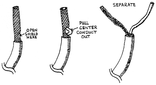
6. This version of the dipole will be fed with coax cable. For 100 ft runs or greater choose RG-8 or similiar for 14 MHz and above and RG-58 for below 14 MHz. For less then 50ft, RG-58 will be adequate for 30 MHz and below. RG-8M style coax will be adequate for up to 100 ft lengths below 30 MHz. Prepare the antenna end of the coax by first cutting the vinyl off of above 4 inches of the end of the coax. Next, with some needle nose pliers reach in between the braids of the outer shield and grap the center conductor and its dielectric. Do this near where the vinyl starts again. You should be able to pull the center conductor out from within the shield. This should leave you with two seperate conductors.


Nilai-Standar-Resistor


17.4.14

Capacitor code table

Capacitor code table

European capacitor material codes

FKC = metal foil and polycarbonate
FKP = metal foil and polypropylene
MKC = metallized polycarbonate foil
MKI = metallized polyphenylene sulphide
MKP = metallized polypropylene
MKS = polystyrene (metallized or with foil)
MKT = metallized polyester foil

Decoding capacitor codes

Looking at our capacitor we will see its marked 474J, this should be read as follows, 47 times the value that can be found in Table 1 corresponding to the 3rd number, in this case 10000. 47 * 10000 = 470000 pF = 470 nF = 0.47 uF with the J meaning a 5% tolerance. A second letter will be a temperature coefficient if its present. Judging by a capacitors size and type, you will quickly learn to determine if the value on the capacitor is given in pF, nF or uF.
If a capacitor is f.ex. marked 2A474J, the capacitance is decoded as described above, the two first signs is the voltage rating and can be decoded from table 2 here below. 2A is 100VDC rating according to the EIA standard.
Some capacitors are only marked 0.1 or 0.01, mostly in these cases the values are given in uF.
Some small capacitance capacitors can be marked with a R between numbers, f.ex. 3R9 where R is a indicator of values below 10pF and have nothing to do with resistance. 3R9 would be 3.9pF.
Table 1
3rd numberMultiply withLetterTolerance
01D0.5pF
110F1%
2100G2%
31,000H3%
410,000J5%
5100,000K10%
61,000,000M20%
7Not usedM20%
80.01P+100%/-0%
90.1Z+80%/-20%

Table 2 – Electronic Industries Alliance (EIA) – voltage code table
0G = 4.0VDC0L = 5.5VDC0J = 6.3VDC
1A = 10VDC1C = 16VDC1E = 25VDC
1H = 50VDC1J = 63VDC1K = 80VDC
2A = 100VDC2Q = 110VDC2B = 125VDC
2C = 160VDC2Z = 180VDC2D = 200VDC
2P = 220VDC2E = 250VDC2F = 315VDC
2V = 350VDC2G = 400VDC2W = 450VDC
2H = 500VDC2J = 630VDC3A = 1000VDC

Here is a list of common capacitors and a scale between the different grades of the Farad SI unit.
Table 3
pico-farad
(pF)
nano-farad
(nF)
mikro-farad
(mF,uF eller mfd)
Capacitor code
10.0010.000001010
1.50.00150.00000151R5
2.20.00220.00000222R2
3.30.00330.00000333R3
3.90.00390.00000393R9
4.70.00470.00000474R7
5.60.00560.00000565R6
6.80.00680.00000686R8
8.20.00820.00000828R2
100.010.00001100
150.0150.000015150
220.0220.000022220
330.0330.000033330
470.0470.000047470
560.0560.000056560
680.0680.000068680
820.0820.000082820
pFnFuFCode
1000.10.0001101
1200.120.00012121
1300.130.00013131
1500.150.00015151
1800.180.00018181
2200.220.00022221
3300.330.00033331
4700.470.00047471
5600.560.00056561
6800.680.00068681
7500.750.00075751
8200.820.00082821
10001 or 1n0.001102
15001.5 or 1n50.0015152
20002 or 2n0.002202
22002.2 or 2n20.0022222
33003.3 or 3n30.0033332
47004.7 or 4n40.0047472
50005 or 5n0.005502
56005.6 or 5n60.0056562
68006.8 or 6n80.0068682
1000010 or 10n0.01103
1500015 or 15n0.015153
2200022 or 22n0.022223
3300033 or 33n0.033333
4700047 or 47n0.047473
6800068 or 68n0.068683
pFnFuFCode
100000100 or 100n0.1104
150000150 or 150n0.15154
200000200 or 200n0.20204
220000220 or 220n0.22224
330000330 or 330n0.33334
470000470 or 470n0.47474
6800006800.68684
100000010001.0105
150000015001.5155
200000020002.0205
220000022002.2225
100000001000010106

3.1.14

Colt RadioCB Tunning

COLT RADIOS
 Model Modulation AM Power SSB Power
 SX33 RV2 or Remove C96 L7 L11 L12 
190 R71  
210 RV201 or Cut D203 L305 L306 
222 RV201 or Cut D203 L305 L306 
290 RV2 or Remove C96 L7 L11 L12 
320DX RV14 RV13 RV12 RV4
320FM RV14 RV13 RV12 RV4
350 RV121 or Cut D19 & D20 L34 L37 
355 RV201  
357 (new) VR4 L11 L12 L13 
 357 (old) RV3 L5 
390 RV2 or Remove C96 L7 L11 L12 
444 Remove C99 L12 L15 L16 (HI PWR) 
480 RV12 or Remove Q37 & Q38 VR4 RV11 RV2
485 RV12 or Remove Q37 & Q38  VR4 RV11 RV2
485DX RV12 or Remove Q37 & Q38 VR4 RV11 RV2
510 RV201 or Cut D203 L304 L305 L306 
800 RV2 or Remove C96 L7 L11 L12 
870 RV2 or Remove C96 L7 L11 L12 
870 (export) RV2 or Remove C96  L7 L11 L12 
1000 RV12 or Remove Q37 & Q38 VR4 RV11 RV2
1200 RV12 VR9 VR2
1200 DX RV14 RV13 RV12 RV4
1600 DX RV12 RV11 RV6 RV3
2000 DX RV12 RV11 RV6 RV3
2400 RV12 RV11 RV6 RV3
EXCAIBUR (EPT30010Z Board) VR14 or Cut R249 VR13 VR12
EXCALIBUR (PTBM121D4X Board) RV14 RV13 RV12 RV4

Superstar CB Radio Tunning

SUPERSTAR RADIOS
  Model Modulation AM Power SSB Power
 120 Remove C99 L15 L16 (HI PWR
 1700 VR14 or Cut R249 VR13 VR12
 1700 B RV12 L15 L16 (HI PWR)
 1700 S RV12 L15 L16 (HI PWR)
 2000 RV12 RV11 RV6 RV3
 2200 RV12 RV11 RV6 RV3
 360 Cut R104 VR6
 3600 VR14 or Cut R249 VR13VR12
 360FM VR14 or Cut R301 VR13VR7
 3900 VR14 or Cut R249 VR13VR12
 95 Remove C99 L15 L16 (HI PWR

Hygain CB Radio Tunning

HY-GAIN RADIOS
 Model Modulation AM Power SSB Power
 2679A RV102 or Cut D111 L110 L109
 2680 RV102 or Cut D111 L110 L109
 2681 RV102 or Cut D111 L110 L109
 2682 RV102 or Cut D111 L110 L109
 2683 RV102 or Cut D111 L110 L109
 2701 RV102 or Cut D111 L110 L109
 2702 RV2 or Remove C96 L7 L11 L12
 2703 RV2 or Remove C96 L7 L11 L12
 2705 Remove Q37 & Q38 VR4 RV2
 2710X RV201 or Cut D111 L106 L109 L110
 2720 RV201 or Cut D111 L106 L109 L110
 2795 RV14 RV13 RV12 RV4
 2795-DX RV14 RV13 RV12 RV4
 3077 RV2 or Cut D10 L9 L8
 670B RV2 or Cut D10 L7 L8 L9
 670B-PR RV2 or Cut D10  L7 L8 L9
 672B RV2 or Cut D10 L7 L8 L9
 8795 (V) RV12 RV11 RV6 RV3
 HYGAIN 16 (2716) RV2 or Remove C209 L109 L110
 HYGAIN 9 (2679) RV102 or Cut D111 L110 L109
 HYGAIN I RV102 or Cut D111 L110 L109
 HYGAIN II RV102 or Cut D111 L110 L109
 HYGAIN VII RV2 or Remove C96 L7 L11 L12
 HYGAIN VIII (3078) RV7 or Cut D301 RV608 RV8 RV5
 HY-RANGE I Cut D6 D10 D11
 HY-RANGE IA RV102 or Cut D111 L110 L109
 HY-RANGE II Cut D6 D10 D11
 HY-RANGE IIA RV102 or Cut D111 L110 L109
 HY-RANGE III RV103 L110 L111 VC2

zte c300 trunk mode

  gpon   profile tcont PPPOE type 4 maximum 9900000   profile tcont 100M type 4 maximum 100000   profile tcont 50M-TRUNK type 4 maximum 5000...