

7MHz helical antenna φ15mm Preparation Example

fabrication example 7MHz helical antenna using the glass rod of φ15mm we will continue to introduce along with the parts description. This antenna is can be produced by a helical handy size of around 1m ~ 1.2m.

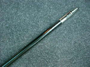
(Upper left) φ3mm element tip mounting bracket \ 100
(center) φ3 × 500mm stainless element \ 600 element is used to cut, if necessary at the time of the adjustment. Element tip mounting bracket, then fixed by press fitting (hammering). Since the removal of the post-mounting is not possible, install it after the last adjustment is complete. Lower right is the attached image.

φ9-φ3mm element adjustment bracket \ 500 is a bracket to attach to the glass rod top. The inner diameter of the large hole φ9mm, has become a small inner diameter of the hole is φ3mm, φ3mm side, can be fixed with screws from the side.
φ15.5-φ8.5 × 1180mm glass rod of the image I have sold out. Rod that is handled currently is glass rod of φ16-φ9 × 1300mm.

φ15mm insulation base connector and the center pin of the M-type connector, is a type of sleeve portion of the above is conducting from the black insulator

It has been applied threaded to help you add a matching coil and condenser in with later in this antenna.

φ1.0mmPEW wire in this antenna I've used about 26 meters

Heat shrinkable tube of Mitsubishi Plastics sebum is the tube (R). This time, we used two because in it is not possible to cover the whole single (size) (size). Ori径29.5mm φ18mm → φ12mm (1m) Ori径23mm φ14mm → φ9mm (1m)
The glass rod, attach the element mounting bracket was cut is the thickness at the position of a little less than φ9mm. The mounting I use an epoxy resin based adhesive. If you want to use as long as possible with a glass rod, it was cut at the position of the little bracket loose position, and attach it plenty with the adhesive. Conversely, it was cut in a little bracket tight position if you want to finish as short as possible, in some cases you can attach the bracket by adjusting the thickness of a sand paper.

Similarly, a glass rod, the thickness Attach the insulation base connector is cut at the position of about φ15mm.

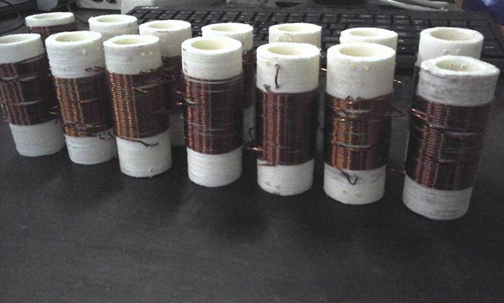
By soldering the wires to the adjustment bracket, we will wound the wire.Winding start is wound a few turns rough, then wound tightly about 21m minutes.

We will continue to the rest of the wire to the interval winding. You can clean interval winding When involving the wire of the same thickness together.

As last 50cm ~ 1m is in the rough winding, and then soldered to the insulating connector. Here once, leave the provisional adjusted mounting elements. Leave close to the element length of preference to cut the wire as needed. As Notes for adjustment, when it was condensed adjustment elements, beyond the position of the position or B in A SWR value is deteriorated or the resonant frequency may deviate significantly. In such a case, by cutting the element at the position of A, ensure that fit the position of the right image when attaching. Provisional adjustment covered with a heat-shrinkable tubing When you have finished. First of all, it is covered with a heat-shrinkable tubing from thicker (lower).
  
Then we will put the thinner the (person above). When cover thinner and can be shorten by superimposing more than 1 ~ 2cm in heat-shrinkable tubing which is placed over the thicker.

Finally, it is complete with the up and down is not final adjustment the adjustment element. In this case, the adjustment for the element we were able to adjust the position of about 17cm. Add the matching coil and a capacitor, if necessary.
|

