
21.12.13
BITX20 Ver.3
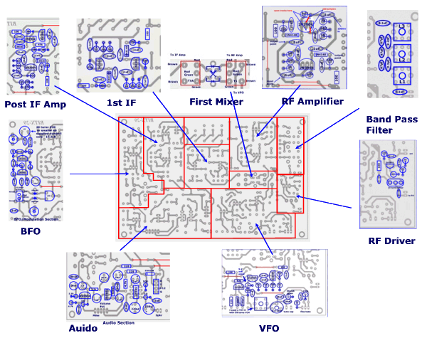
The board can be broken into sections and then built and tested one section at a time. This will make troubleshooting easier as any problems will be confined to one small section.
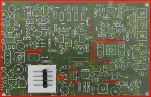
Install all of the wire jumpers onto the board. These can use bare or insulated wire. #22 wire will fit nicely through the holes. Place the jumpers where indicated by the red lines. If you have access to some header pins for the 4 pin power connector, it will make testing of the board a little easier as you can plug and unplug the wires between testing steps. We will be applying voltage to different pins of the 4 pin power connector to test the receiver and transmitter. This connector is to the right of the header pins and circled in the picture below. If you don't have the pins, a spdt switch or regular wires can be used.
Applying power to the R pin activates the receiver circuits. To the T pin activates the transmitter circuits. The V terminal activates the common circuits such as the BFO and the VFO. This will all be done automatically later by the PTT relay on the PA board.
When measuring current, place the + lead of the MA meter on the + terminal of the power supply and connect the - lead of the meter to the pin designated for power application called for by the instructions. This should be the R , T, or V pin of the power connector. The R and T pins should never be powered at the same time! The - lead of the power supply connects to ground on the board.
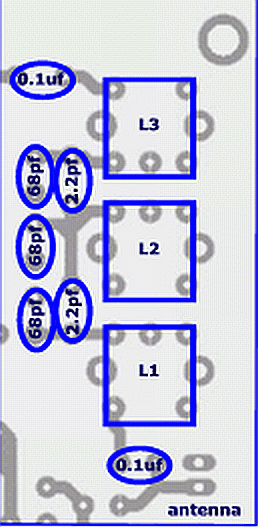
Band Pass Filter SectionFor the band pass filter section you will need the following components.
Band pass Filter Components
| |||
quantity
|
value
|
description
| |
3
|
L1, L2, L3
| provided with boards | |
2
|
0.1ufd
| capacitors | |
2
|
2.2pfd
| capacitors, npo | |
3
| capacitors, npo | ||
Using the parts placement diagram below, assemble the band pass filter section. Be very careful when inserting the transformers into the board. If the pins are misaligned, they will be pushed back into the can and are hard to retrieve. It is easiest to insert the 3 pin side first. Before you seat the can flush to the board, inspect the bottom side of the board and insure all pins are protruding. If a pin is pushed back, very carefully pull it back out with a pair of needle nose pliers.
After we assemble the next section, the RF amplifier, we can test it using a sweep generator. We will wait until then because it will provide the proper load impedance to the filter. If you don't have a sweep generator and oscilloscope, you can perform a basic alignment after the exciter is completed using an audio input and the exciter as an RF signal source. More on that procedure later.
RF Amplifier Section
For the RF amplifier section you will need the following components.
For the RF amplifier section you will need the following components.
RF Amplifier Components
| ||||
quantity
|
value
|
description
|
color code
| |
2
|
10 ohm
| resistors | brn-blk-blk | |
2
|
100 ohm
| resistors | brn-blk-brn | |
4
|
220 ohm
| resistors | red-red-brn | |
2
|
1k
| resistors | brn-blk-red | |
2
|
2.2k
| resistors | red-red-red | |
8
|
.1uf
| capacitors | ||
2
|
1N4148
| diodes | ||
1
|
2N3904
| transistor | ||
1
|
2SC2570A
| furnished with boards | ||
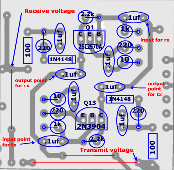
Using the parts placement diagram below, assemble the RF amplifier section.
Note:
Install the transistors with the flat as shown on the drawing. The board silkscreen is not correct for 2N3904's. It is correct, however, for the 2SC2570A. Also, the 2SC2570A pins are not configured the same as the 2N3904's so is not directly interchangeable.
Install the transistors with the flat as shown on the drawing. The board silkscreen is not correct for 2N3904's. It is correct, however, for the 2SC2570A. Also, the 2SC2570A pins are not configured the same as the 2N3904's so is not directly interchangeable.
Note:
When setting the power supply voltage to measure the current, if you have 2 meters, hook one up as the ma meter and then meausre the voltage using the other where it enters the board. ma meters have an internal voltage drop and if you set the power supply to 13.25 volts, there will be less voltage at the board due to the meters voltage drop.
When setting the power supply voltage to measure the current, if you have 2 meters, hook one up as the ma meter and then meausre the voltage using the other where it enters the board. ma meters have an internal voltage drop and if you set the power supply to 13.25 volts, there will be less voltage at the board due to the meters voltage drop.
After assembly, apply 13.25 volts to the Receive voltage test point. The measured current should read approximately 11.7 ma's
Measure the Q1 voltages and compare to the chart below. There is space to document your readings after the standard voltages.
Measure the Q1 voltages and compare to the chart below. There is space to document your readings after the standard voltages.
Disconnect the receive voltage line and connect the 13.25 volts to the Transmit voltage point. Warning! Do not ever have voltage applied to the Receive and Transmit point simultaneously! The measured current should read approximately 11.9 ma's .
ma's
|
Measure the Q13 voltages and compare to the chart below.
Transistor voltages with 13.25 volts applied
| |||||
Receive - Q1 voltages
|
Transmit - Q13 voltages
| ||||
Collector
|
8.76
|
Emitter
|
2.008
| ||
Emitter
|
1.995
|
Base
|
2.703
| ||
Base
|
2.711
|
Collector
|
8.69
| ||
For the VFO section you will need the following components.
VFO Components
| ||||
quantity
|
value
|
description
|
color code
| |
1
|
10 ohm
| resistor | brn-blk-blk | |
3
|
100 ohm
| resistors | brn-blk-brn | |
4
|
1k
| resistors | brn-blk-red | |
1
|
2.2k
| resistor | red-red-red | |
1
|
4.7k
| resistor | yel-vio-red | |
2
|
10k
| resistor | brn-blk-orn | |
1
|
220k
| resistor | red-red-yellow | |
1
|
10pf npo
| capacitor | ||
1
|
220pf npo
| capacitor | ||
2
|
560pf npo/polystyrene
| capacitor | ||
5
|
.1uf
| capacitors | ||
1
|
6.5-30pf
| variable capacitor | ||
3
|
2N3904
| transistor | ||
1
|
1N5239A or equiv 9.1 volt
| zener diode | ||
1
|
1N4752A or equiv 33 volt
| zener diode | ||
1
| T37-6 with 50 turns #34 - 7.5 uh | toroid coil | ||
Using the parts placement diagram below, assemble the VFO section.
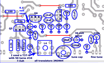
After assembly, apply 13.25 volts to the Voltage test point. The measured current should read approximately 44.8 ma's
ma's
|
Measure Q5, and Q6 voltages and compare to the chart below. Your voltages may be slightly higher as my 9.1 volt zener is only 8.48. You can't measure the Q7 voltages until T1 is installed.
| Transistor voltages with 13.25 volts applied | ||||
Q5
|
Q6
| |||
| Emitter |
3.56
|
2.84
| ||
| Base |
4.23
|
3.52
| ||
| Collector |
8.48
|
8.48
| ||
Mixer Section
For the mixer section, you will need the following components.
Mixer Components
| |||
quantity
|
value
|
description
| |
4
|
1N4148
| diode | |
3
|
FT37-43 cores or supplied binocular cores
| T1, T1a, and T2 | |
First we need to wind the trifilar transformers. You will need 2 for the mixer circuit and 1 more for the BFO so you might as well make all 3 now as they are all the same. All 3 will be on FT37-43 cores with 8 turns trifilar windings using #26 - #30 wire. You can find a video on winding trifilar transformers at
The transformers may be wound using either the supplied binocular cores or FT37-43 cores. You can investigate further by reading Wide-Band Transformers In the Bitx Instructions are included for both.
Use FT37-43 cores with 8 turns of trifilar wire. This will take 7" of trifilar wire for each transformer. 1 turn is 1 pass thru the center. We need 3 transformers total. 2 for the mixer and 1 for the BFO. I used red, green, and brown #28 wire but anything from #26 - #30 should be fine as size doesn't make much difference as long as it will fit into the core. The different colors make keeping the windings straight easier. When pulling the wire through the holes in the cores, be careful not to scrape the insulation off.
\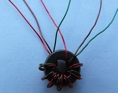 .
.
.
When you are through winding, it should look like this. Use the red wire from the right side of the picture and take the green wire from the left side of the picture and twist them together. This forms the center-tapped windings. If your wire is not heat strippable, strip of the insulation before twisting them together.
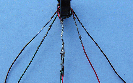
After tiinning, it should look like this. Install both transformers. Do not install the diodes yet.
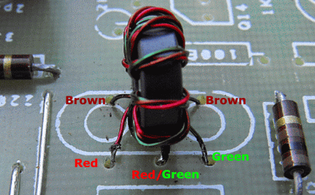
Installed, T1 should look like this.
Using the supplied binocular cores
Use the binocular cores and wind 8 turns of trifilar wire onto the cores. 1 turn is a trip through both holes ending up where you started. We need 2 transformers. I had red, green, and brown #28 wire. The original drawing called for #32 but the size doesn't make much difference as long as it will fit into the core. The different colors make keeping the windings straight easier. When pulling the wire through the holes in the cores, be careful not to scrape the insulation off. The binocular cores can have sharp edges. When you are done, it should look like this.
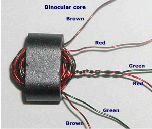
The completed transformer should look like this. Yours won't look so full as this one actually had 13 turns from and earlier build. Use 8 turns only though.
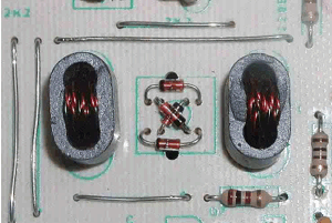
The installed binocular transformers should look like this. Do not install the diodes yet. Wait untill after you have performed the test below.
After winding and installing both transformers, verify continuity using an ohmmeter. There should be 0 ohms between the following points for both T1 and T1a. This step insures that the insulation was removed properly and you have good solder connections. Failure to completely remove the insulation may result in a faulty solder joint. This is a common failure item.
brown
|
brown
|
0 ohms
| |
green
|
red-green or center tap
|
0 ohms
| |
red-green or center tap
|
red
|
0 ohms
|
Now we can measure the Q7 voltages. Apply 13.25 volts to the Voltage test point. The measured current should read approximately 84 ma's
ma's
|
Q7
| ||
3.71
| ||
4.40
| ||
8.85
| ||
If you have an oscilloscope, using a x10 probe, connect to the collector of Q7.
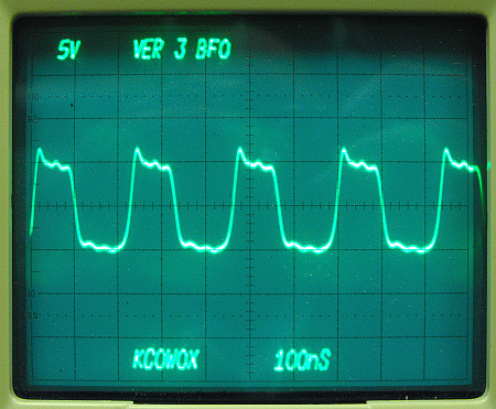
The frequency should be variable using the tuning capacitor. I have a 10-365pfd variable and the frequency will vary from 3.8mhz to 4.8mhz. We will trim the frequency to the proper range later.
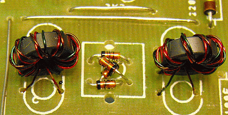
Using the parts placement diagram below, install the 4 diodes observing the proper polarity. The band is the cathode end.
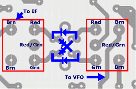
Bend the leads and position them observing the black bands as shown below.
Q7 collector waveform now is:
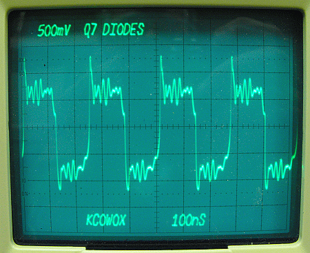
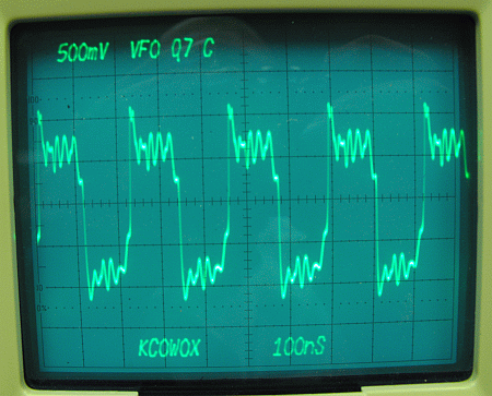
The signal is clipped to +/- about .7 volts as the diodes bias on. If the waveform wasn't clipped or only clipped on one side, the problem would be an open in the diode circuit or a bad diode.
1st IF Amplifier Section
This is almost an exact duplicate of the RF Amplifier section. For the 1st IF Amplifier section you will need the following components.
1st IF Amplifier Components
| ||||
quantity
|
value
|
description
|
color code
| |
2
|
10 ohm
| resistors | brn-blk-blk | |
2
|
100 ohm
| resistors | brn-blk-brn | |
4
|
220 ohm
| resistors | red-red-brn | |
2
|
1k
| resistors | brn-blk-red | |
2
|
2.2k
| resistors | red-red-red | |
8
|
.1uf
| capacitors | ||
2
|
1N4148
| diodes | ||
2
|
2N3904
| transistors | ||
Using the parts placement diagram below assemble the 1st IF amplifier section.
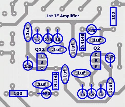
After assembly, apply 13.25 volts to the Receive voltage test point and the voltage test point. The measured current should read approximately 109.2 ma's
ma's
|
Measure the Q2 voltages and compare to the chart below.
Disconnect the receive voltage line and connect the 13.25 volts to the Transmit voltage point.
Warning! Do not have voltage applied to the Receive and Transmit point simultaneously!
The measured current should read approximately 109.2 ma's
ma's
|
Measure the Q13 voltages and compare to the chart below.
Transistor voltages with 13.25 volts applied
| |||||
Q2 voltages
|
Q12 voltages
| ||||
Collector
|
8.74
|
Collector
|
8.76
| ||
Base
|
2..708
|
Base
|
2.696
| ||
Emitter
|
1.988
|
Emitter
|
1.970
| ||
Q2 and Q12 circuits are identical so the differences in measured voltages are due to component tolerances.
2nd IF Amplifier
We are going to skip the crystal filter for now. To check our crystals and match them we need an oscillator. We will have one after we complete the BFO section. Also, this is a good spot to leave open to allow easy testing with test equipment later.
We will need the following components for the 2nd IF Amplifier.
2nd IF Amplifier Components
| ||||
quantity
|
value
|
description
|
color code
| |
1
|
4.7 ohm
| resistor | yel-vio-gld | |
1
|
22 ohm
| resistor | red-red-blk | |
2
|
100 ohm
| resistors | brn-blk-brn | |
4
|
220 ohm
| resistors | red-red-brn | |
2
|
470 ohm
| resistor | yel-vio-brn | |
2
|
1k
| resistors | brn-blk-red | |
1
|
2.2k
| resistors | red-red-red | |
1
|
10k
| resistor | brn-blk-org | |
1
|
47k
| resistor | yel-vio-org | |
8
|
.1uf
| capacitors | ||
2
|
1N4148
| diodes | ||
3
|
2N3904
| transistors | ||
Using the parts placement diagram below assemble the 2nd IF amplifier section.
Note: The 4.7 ohm resistor in the drawing below is correct. The silkscreen on the board may show 10e. Use a 4.7 ohm here.
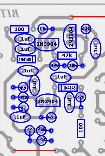
Apply 13.25 volts to the receive line and the voltage line.The measured current should be approximately 124.7 ma's.
ma's
|
Measure and verify the voltages in the chart below for Q3 and Q3A.
Receive transistor voltages with 13.25 volts applied
| |||||
Q3
|
Q3A
| ||||
Collector
|
6.08
|
Collector
|
10.78
| ||
Base
|
.71
|
Base
|
6.07
| ||
Emitter
|
0
|
Emitter
|
5.35
| ||
Remove the voltage from the receive line and apply it to the transmit line The measured current should be approximately 117 ma's. Measure and verify the voltages in the chart for Q11.
Transmit transistor voltages with 13.25 volts applied
| ||
| Q11 | ||
| Collector | 9.90 | |
| Base | 3.118 | |
| Emitter | 2.405 | |
BFO Section
We will need the following components for the BFO section.
BFO Section Components
| ||||
quantity
|
value
|
description
| ||
1
|
100 ohm
| resistor | brn-blk-brn | |
3
|
1k
| resistors | brn-blk-red | |
1
|
120k
| resistor | brn-red-org | |
1
|
10pf
| capacitor - npo | ||
1
|
22pf
| capacitor - npo | ||
2
|
23pf
| variable capacitors | ||
2
|
220pf
| capacitor - npo | ||
1
|
.001uf
| capacitor | ||
2
|
.1uf
| capacitors | ||
1
|
50uf
| capacitor | ||
1
|
10 mhz
| crystal | ||
1
|
7.5uh
| inductor (see text) | L5 | |
1
|
100 ohm
| potentiometer | ||
1
|
T2
| transformer (see text) | ||
2
|
1N4148
| diodes | ||
2
|
2N3904
| transistors | ||
2
|
socket pins
| |||
We wound T2 earlier in the mixer section. If you didn't at that time, refer back the the mixer section for directions.
Using the parts placement diagram below assemble the BFO section. If you can obtain 2 plug in socket pins for the crystal, we will use the bfo oscillator to help match the crystal filter crystals frequency before we build the crystal filter.
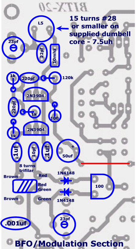
After assembly, apply 13.25 volts to the Voltage test point and ground to the ground point. We don't need any voltage on the Rx or Tx as the BFO runs all of the time.
The measured current should read approximately 98.6 ma's
ma's
|
Measure Q8 and Q9 voltages and compare to the chart below.
Transistor voltages with 13.25 volts applied
| |||||
Q8 voltages
|
Q9 voltages
| ||||
Collector
|
11.99
|
Collector
|
11.99
| ||
Base
|
6.41
|
Base
|
6.30
| ||
Emitter
|
6.32
|
Emitter
|
5.81
| ||
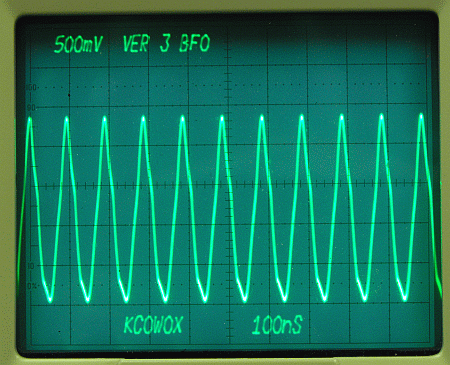
If you have an oscilloscope, connect as shown below to see the bfo output waveform.
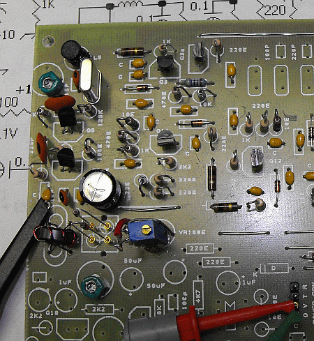
You should see the waveform below.
If you have a frequency counter, an easy way to get the correct frequency range is a test hookup shown below. Using this method, wind a couple of extra windings on the dumbell core and install it using a test plug made from an cut up IC socket. This will prevent damaging the board with repeated soldering/desoldering operations. A good place to connect the counter is at the junction of T2 and the 0.1uf cap as shown in the picture above. Apply power and adjust the variable cap to the middle of it's range. Remove a turn or two until the frequency is near 9,995,268 hz. This should be close enough that it should adjust properly later.
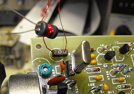
My BFO frequency, when adjusted properly for the filter on my board, was 9,995,268 hz.
If you don't have access to a counter, just wind the 15 turns on the core.
Audio Section
We will need the following components for the Audio Section.
Audio Section Components
| ||||
quantity
|
value
|
description
| ||
1
|
10 ohm
| resistor | brn-blk-blk | |
1
|
100 ohm
| resistor | brn-blk-brn | |
2
|
220 ohm
| resistors | red-red-brn | |
2
|
2.2k
| resistors | red-red-red | |
2
|
4.7k
| resistors | yel-vio-red | |
1
|
10k
| resistor | brn-blk-org | |
1
|
120k
| resistor | brn-red-yel | |
1
|
100pf
| capacitor | ||
2
|
.001uf
| capacitors | ||
2
|
.1uf
| capacitors | ||
4
|
1uf
| capacitors | ||
3
|
50uf
| capacitor | ||
2
|
220uf
| capacitors | ||
1
|
LM386
| audio amp IC | ||
1
|
1N4148
| diode | ||
2
|
2N3904
| transistors | ||
Using the parts placement diagram below assemble the audio amplifier section.
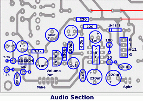
After assembly, apply 13.25 volts to the Voltage test point, the Rx test point, and ground to the ground point. Do not connect the volume control pot or the speaker. The measured current should read approximately 146 ma's
ma's
|
Measure the Q4 voltages and compare to the chart below.
Transistor voltages with 13.25 volts applied
| |||||
Q4 voltages
|
Q10 voltages
| ||||
Collector
| 2.234 |
Collector
| 9.16 | ||
Base
| .709 |
Base
| 4.18 | ||
Emitter
| 0 |
Emitter
| 3.50 | ||
Remove the voltage from the RX test point and apply it to the TX test point. Leave the voltage applied to the V test point and measure the Q10 voltages and compare to the chart above.
Crystal Filter
We will need the following components for the crystal filter.
Crystal Filter Components
| |||
quantity
|
value
|
description
| |
2
|
100pf
| capacitors | |
1
|
220pf
| capacitor | |
4
|
10 mhz
| crystals | |
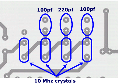
If you have access to a frequency counter, the crystals should be matched as close as possible in frequency. This is done by inserting them into the BFO circuit and counting the frequency. This is best done using at least 10 crystals.
Assemble the crystal filter using the drawing below.
Output Driver
We will need the following components for the output driver.
Output Driver Components
| ||||
quantity
|
value
|
description
| ||
1
|
10 ohm
| resistor | brn-blk-blk | |
2
|
100 ohm
| resistors | brn-blk-brn | |
1
|
1k
| resistor | brn-blk-red | |
1
|
2.2k
| resistor | red-red-red | |
4
|
.1uf
| capacitors | ||
1
|
2N3904
| transistor | ||
1
|
transformer
| FT37-43 | ||
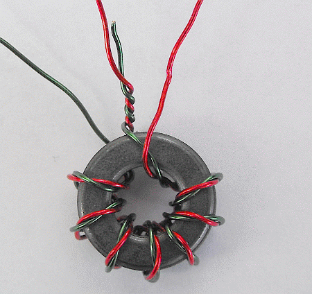
The transformer may be made using a FT37-43 core. Wind 8 bifilar turns on the core . This will take 6" of wire. Take the left side red and the right side green and twist together to form the center tap.
Assemble the components as shown below.
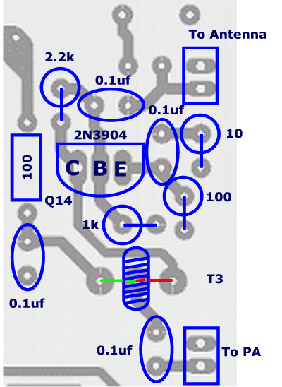
After assembly, apply 13.25 volts to the Voltage test point the Tx test point, and ground to the ground point. The measured current should read approximately 159 ma's
ma's
|
Measure the Q44 voltages and compare to the chart below.
| Q14 | ||
| Collector | 10.58 | |
| Base | 3.19 | |
| Emitter | 2.47 | |
Test and alignment
Connect the variable tuning capacitor to the board. Apply power to the voltage connection. Do not apply to the Rx or Tx connector.
The following readings will confirm operation of the BFO and the VFO.
Communications receiver method::
BFO
Move the wire nesr Q9 and Q9 and tune the receiver around 9.996 mhz. Verify that the signal you are receiving is your board by turning off the power to your board.
Move the wire nesr Q9 and Q9 and tune the receiver around 9.996 mhz. Verify that the signal you are receiving is your board by turning off the power to your board.
VFO
Move the wire near Q6 and Q7. Tune the receiver in the 4.150 to 4.350 range. Verify that the signal you are receiving is your board by turning off the power to your board.
Move the wire near Q6 and Q7. Tune the receiver in the 4.150 to 4.350 range. Verify that the signal you are receiving is your board by turning off the power to your board.
Using a "Sharpie" RF probe or scope:
Using a "Sharpie" RF Probe as detailed at http://golddredgervideo.com/kc0wox/rfprobe.htm you should get the following readings. These readings will be very approximate as the RF Probe readings are more of a presence and magnitude reading.:
Using a "Sharpie" RF Probe as detailed at http://golddredgervideo.com/kc0wox/rfprobe.htm you should get the following readings. These readings will be very approximate as the RF Probe readings are more of a presence and magnitude reading.:
RF Probe
BFO junction of primary T2 and capacitor - .674 volts
BFO junction of primary T2 and capacitor - .674 volts
Scope
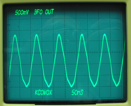
RF Probe
VFO junction of Q6 emmiter and 1k resistor - 1 volt
VFO junction of Q6 emmiter and 1k resistor - 1 volt
Scope
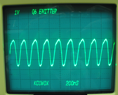
RF Probe
VFO collector of Q7 - .59 volts.
VFO collector of Q7 - .59 volts.
Scope
Aligning the BFOThe proper BFO frequency will end up around 9.9953mhz. Connect the frequency counter to the emitter of Q9. You should have a tuning range of around 15khz. You can raise the frequency by removing turns from L5. If your frequency is too high, you can add capacitance in parallel with the trimmer capacitor. Once you get the frequency close, verify it this way.
Connect your "sharpie" RF probe to the PA output point.
Connect power to the transmit point.
Adjust the carrier balance pot to one end and note the reading.
Adjust it to the other end.
Set it to the end that gave the most voltage out.
Adjust the BFO frequency while watching the voltage reading until a peak is reached.
At this point the BFO is adjusted to the top of the lower skirt of the filter.
Connect power to the transmit point.
Adjust the carrier balance pot to one end and note the reading.
Adjust it to the other end.
Set it to the end that gave the most voltage out.
Adjust the BFO frequency while watching the voltage reading until a peak is reached.
At this point the BFO is adjusted to the top of the lower skirt of the filter.
Note the reading and then adjust the BFO frequency back down until it reads about 0.45 of the maximum reading. This will set it about 7-8 db down the filter skirt.
This setting is as close as we can get until we add modulation.
Aligning the VFO
Connect the counter to the emitter of Q6. Verify the tuning range of the VFO. If it is too low, remove turns from L4. If it is too high, add capacitance in parallel with the 220pf capacitor. If it has too wide a tuning range, add capacitance in series with the variable tuning capacitor. Use only npo capacitors or the VFO may drift excessively.
Connect the counter to the emitter of Q6. Verify the tuning range of the VFO. If it is too low, remove turns from L4. If it is too high, add capacitance in parallel with the 220pf capacitor. If it has too wide a tuning range, add capacitance in series with the variable tuning capacitor. Use only npo capacitors or the VFO may drift excessively.
Aligning the Bandpass Filter
Adjust the VFO frequency to 4.250mhz.
The easiest way with no test equipment is while in receive, connect an antenna to the RX Ant point and adjust the filter transformers for maximum volume out. This is probably the easiest way and can be refined later after the PA is connected.
Alternate way 1:
W hile in transmit and monitoring the PA Output voltage at the left hand side of the 0.1ufd that is connected to T3, labeled "To PA" in the exciter schematic, with an RF probe or oscilloscope, adjust the 3 transformers for the maximum displayed voltage.
Alternate way 1:
W hile in transmit and monitoring the PA Output voltage at the left hand side of the 0.1ufd that is connected to T3, labeled "To PA" in the exciter schematic, with an RF probe or oscilloscope, adjust the 3 transformers for the maximum displayed voltage.
Alternate way 2:
Monitor the power supply current while in transmit and adjust the transformers for maximum current. If you can't see any variation, adjust the carrier balance pot to one end. This will insert carrier and cause the output voltage or the power supply current to increase.
Monitor the power supply current while in transmit and adjust the transformers for maximum current. If you can't see any variation, adjust the carrier balance pot to one end. This will insert carrier and cause the output voltage or the power supply current to increase.
Now readjust the carrier balance and the balance capacitor for minimum voltage reading. We will refine this setting after the linear is connected.
The alignment of the exciter is now done.
sumber :
16.3.12
Internet Explorer for Mac the Easy Way: Run IE 7, IE8, & IE9 Free in a Virtual Machine
Internet Explorer for Mac the Easy Way: Run IE 7, IE8, & IE9 Free in a Virtual Machine
Sep 4, 2011 - 203 Comments

If you’re a Mac user that requires the usage of Internet Explorer under Mac OS X, you’ll find your choices are generally as follows: run IE on top of Mac OS X with Wine which can be slow and buggy, dual boot Windows and Mac OS X which is a nuisance because it requites rebooting, or use virtualization with something like Parallels, VMWare, or VirtualBox. Virtualization is generally the best method because you can run IE and other Windows apps directly atop OS X, but some of the VM software is expensive and you still need a Windows license key, right? Wrong!
Run Internet Explorer 7, 8, and 9 in Mac OS X the Easy & Free Way
We’re going to walk you through how to install Internet Explorer 7, 8, or 9 in a virtual machine running Windows, directly in Mac OS X – for free. This is achieved by using the freely available VirtualBox software from Oracle, and combining that with free Internet Explorer testing virtual machines from Microsoft, the trick is converting these free IE vm’s so that they work flawlessly under OS X (or Linux, technically), and that is all handled automatically with this method.Notes: the admin password for all of the IE VMs is “Password1″ without the quotes. This has been tested and confirmed to work with Mac OS X 10.7 Lion and Mac OS X 10.6 Snow Leopard.
- Download & Install VirtualBox – Download Now (direct .dmg download link) – visit VirtualBox Downloads page
- Launch the Terminal (located in /Applications/Utilities/)
- Decide which versions of Internet Explorer you want to download and install – each version of Internet Explorer is contained within a separate virtual machine that runs within VirtualBox. In other words, if you want to run Internet Explorer 7, 8, and 9, you will need to download three separate VM’s, which may take a while so keep that in mind. Select the text below and copy it:
-
Install ALL versions of Internet Explorer: IE7, IE 8, and IE 9
-
Install Internet Explorer 7 Only
-
Install Internet Explorer 8 Only
-
Install Internet Explorer 9 Only
- Copy and paste the selected command from above into the Terminal and hit return, this will start the download and conversion process. How long this takes depends on your internet connection and how many versions of Internet Explorer you chose to install
- Launch VirtualBox and boot Windows & Internet Explorer – select the virtual machine corresponding to the version of Internet Explorer you intend to use: IE7, IE8, IE9, then click on the “Start” button to boot that Windows machine with that version of Internet Explorer.
curl -s https://raw.github.com/xdissent/ievms/master/ievms.sh | bash
curl -s https://raw.github.com/xdissent/ievms/master/ievms.sh | IEVMS_VERSIONS="7" bash
curl -s https://raw.github.com/xdissent/ievms/master/ievms.sh | IEVMS_VERSIONS="8" bash
curl -s https://raw.github.com/xdissent/ievms/master/ievms.sh | IEVMS_VERSIONS="9" bash http://osxdaily.com/2011/09/04/internet-explorer-for-mac-ie7-ie8-ie-9-free/
23.12.11
Basic Command of Extreme switch
Basic Command of Extreme switch
Basic’s of the CLISYNTAX HELPER
The CLI has a built-in syntax helper. If you are unsure of the complete syntax for a particular command, enter as much of the command as possible and press [Return]. The syntax helper provides a list of options for the remainder of the command. The syntax helper also provides assistance if you have entered an incorrect command.
COMMAND COMPLETION WITH SYNTAX HELPER
ExtremeWare provides command completion by way of the [Tab] key. If you enter a partial command, pressing the [Tab] key posts a list of available options, and places the cursor at the end of the command.
ABBREVIATED SYNTAX
Abbreviated syntax is the most unambiguous, shortest allowable abbreviation of a command or parameter. Typically, this is the first three letters of the command.
When using abbreviated syntax, you must enter enough characters to make the command unambiguous and distinguishable to the switch.
COMMAND SHORTCUTS
All named components of the switch configuration must have a unique name.
Components are named using the create command. When you enter a command to configure a named component, you do not need to use the whole keyword of the component. For example, to create a VLAN, you must enter a unique VLAN name:
create vlan engineering
Once you have created the VLAN with a unique name, you can then eliminate the keyword vlan from all other commands that require the name to be entered. For example, instead of entering the switch command
config vlan engineering delete port 1:3,4:6
you could enter the following shortcut:
config engineering delete port 1:3,4:6
Similarly, on the Summit switch, instead of entering the command
config vlan engineering delete port 1-3,6
you could enter the following shortcut:
config engineering delete port 1-3,6
SUMMIT SWITCH NUMERICAL RANGES
Commands that require you to enter one or more port numbers on a Summit switch use the parameter in the syntax. A portlist can be a range of numbers, for example:
port 1-3
You can add additional port numbers to the list, separated by a comma:
port 1-3,6,8
NAMES
All named components of the switch configuration must have a unique name. Names must begin with an alphabetical character and are delimited by white space, unless enclosed in quotation marks.
Basics of the Web Browser interface
Each switch has a built in HTTP server that drives the web based GUI interface. To access the GUI interface simply open a web browser and point to the IP Address of the switch. Now the switch has an easy point and click means of configuration.
Things to do with ports on an Extreme switch
Resetting Back to Factory Configs.
To reset the switch back to factory configs, and keep the user account informantion type the command:
Unconf switch
To rest the switch back to factory configs and remove the users account information type the command:
Unconf switch all
Mirroring Ports
Port mirroring configures to the switch to copy all traffic associated with one or more ports. The monitor port can then be connected to a Sniffer or RMON probe for analysis. The traffic filter can be defined based on one of the following criteria:
Physical port – All data that traverses that port, regardless of the VLAN, is copied to the mirror port
VLAN – All data that traverses the VLAN, regardless of the physical port, is copied to the mirror port.
Virtual Post – All data specific to a VLAN on a specific port is copied to the mirror port.
Note: The port you configure to be the mirror port must be active prior to enabling it for mirroring.
The following example selects port 3 as the mirror port and sends all traffic coming into out of port 1 to the mirror port
enable mirroring to port 3
config mirroring add port 1
The following example sends all traffic for the Default VLAN to the mirror port
config mirroring add vlan default
The following example sends all traffic coming into and out of port 1 and the Default VLAN to the mirror port.
config mirroring add port 1 vlan default
To disable mirroring:
Disable mirroring
Naming Ports
You can name switch ports in order to keep track of what is plugged in to them, or for personal records.
To name a port type the command:
Config port display-string
To reset port name type:
unconfig port display-string
Setting Speed and Duplex on a port
To set a port for 100Meg full duplex type the command:
Config port auto off duplex full speed 100
To set a port for 10Meg Half duplex type the command:
Config port auto off duplex half speed 10
To reset the port able to auto negotiation type the command:
Config port auto on
Looking at Port Errors
Note: If you want to look at all ports, simply leave out the port number and the switch will display all ports. Also you can specify port groups. (i.e. port 1-19, 20,34,46, etc)
Show port collision
Show port configuration
Show port info detail
Show port packet
Show port rxerror
Show port stat
Show port txerror
Show port util (use the space bar to scroll through different utilization screens)
Configuring VLANS on an Extreme Switch
With all switches from Extreme Networks there is no need to create a “router interface” in order to use VLANS. Since every port can be a router and the routing mechanism is built into the switch fabric, VLAN configuration has become incredibly easy. When the switch is first started up our of the box, there is a single VLAN called “Default” (VLAN 1) and contains all ports on the switch. If you desire to add ports to other VLANS, you must first delete the port out of the VLAN they are in. (for security purposes).
VLAN Basics
Creating a VLAN
Type the command:
Create vlan Note: the name can be any unique name the user desires.
Giving the VLAN an IP Address
Type the command:
Config vlan ip x.x.x.x /xx Note: The network mask can be either “slash notation” or “dotted decimel”, (i.e. /24 or 255.255.255.0)
Adding ports to that VLAN
Type the command:
Config vlan add port n Note: You can also add multiple ports by using commas or dashes. (i.e. port 1-48 or 1,2,8,10 or 1-10,5-20)
Deleting ports out of a VLAN
Type the command:
Config vlan delete port n
Assigning tags and designating Trunk (uplink) ports
Be default when you add ports to a VLAN, they are added untagged. Most user ports will be untagged. The reason for adding tags to ports is to allow multiple VLAN traffic to traverse those ports, as with trunk ports. Trunk ports (or Uplinks) can contain several thousand VLANS on a single link. This is useful if you have more than one VLAN at an edge switch. In order to have more than one VLAN on a uplink you will need to add an 802.1q tag to port. Please be aware that Cisco’s VLAN numbers should be the same as a standard 802.1q tag number. (I.e. if you want to trunk a Cisco switch using Vlan500 and Vlan600 to another standards based switch, the VLAN tags should match up. Tag 500 and Tag 600 should be on that trunk)
Adding a 802.1q tag to a VLAN
Type the command:
Config vlan add tag Note: this number can be any number between 2 and 4096.
Making a port a “trunk” port
Type the command:
Config vlan add port n tagged
How to load share ports (aka Fast Etherchannel)
To define a load sharing group, you assign a group of ports to a single logical port number.
To enable or disable loadsharing use the following commands.
Enable sharing grouping
To disable sharing:
Disable sharing
For example
Enable sharing 2 grouping 2-8
Routing on an Extreme Networks switch
Every switch from Extreme is a layer 3 switch. To enable routing, obviously you need more than 1 VLAN with an IP address on the switch. Once you have your desired number of VLANS created, with their own unique IP address, you issue a single command to enable routing.
How to turn on routing
Type the command:
Enable ipforwarding
Note: you can also turn on or off routing for any single vlan on the switch.
(i.e. enable ipforwarding vlan or disable ipforwarding vlan )
You are now routing between VLANS.
Routing Protocols (getting routing to work with other switches)
All Extreme Networks switches support static routes, Rip v1/v2, OSPF, BGP and IS-IS. Just like any router you must use a routing protocol in order for routers/switches to share routing information.
Turning on OSPF
Type the command:
config ospf add vlan area 0.0.0.0
This adds each VLAN to the OSPF Area 0
You can also add all the VLANS by typing the command:
Config ospf add vlan all area 0.0.0.0
Now you enable OSPF by typing:
Enable OSPF
You now have OSPF running on your switch.
The following is a sample configuration:
create vlan HQ_10_0_2
create vlan HQ_10_0_3
create vlan LA_161_48_2
create vlan Chi_160_26_26
config vlan HQ_10_0_2 ipaddress 10.0.2.1 255.255.255.0
config vlan HQ_10_0_3 ipaddress 10.0.3.1 255.255.255.0
config vlan LA_161_48_26 ipaddress 161.48.2.26 255.255.255.0
config vlan Chi_160_26_26 ipaddress 160.26.2.1 255.255.255.0
create ospf area 0.0.0.5
create ospf area 0.0.0.6
enable ipforwarding
config ospf area 0.0.0.6 stub nosummary stub-default-cost 10
config ospf add vlan LA_161_48_2 area 0.0.0.6
config ospf add vlan Chi_160_26_26 area 0.0.0.5
config ospf add virtual-link 160.26.25.1 0.0.0.5
config ospf add vlan all
enable ospf
20.12.11
Cisco Configuration Professional
Q.
How do I use Cisco Configuration Professional with an integrated
services router that does not have a factory default configuration?
A. Steps to run Cisco Configuration Professional on a Cisco router with a non-factory default configuration follow:
Step 1. Connect to your router using Telnet or SSH or through the console.
Enter the global configuration mode using the command:
Router(config)#enable
Step 2. Enable the router HTTP or HTTPS server using the following Cisco IOS Software commands.
If
HTTP and HTTPS are enabled and configured to use nonstandard port
numbers, you can skip this step and simply use the port number already
configured.
Router(config)# ip http server
Router(config)# ip http secure-server
Router(config)# ip http authentication local
Note: HTTPS is enabled only for cryptography-enabled Cisco IOS Software images.
Step 3. Create a user with privilege level 15.
Router(config)# username
Note: Replace and with the username and password that you want to configure.
Step 4. Configure SSH and Telnet for local login and privilege level 15:
Router(config)# line vty 0 4
Router(config-line)# privilege level 15
Router(config-line)# login local
Router(config-line)# transport input telnet
Router(config-line)# transport input telnet ssh
Router(config-line)# exit
Step 5. (Optional) Enable local logging to support the log monitoring function:
Router(config)# logging buffered 51200 warning
http://www.static-cisco.com/assets/cdc_content_elements/embedded-video/video-data-sheets/ccp-overview.swf
http://www.static-cisco.com/assets/cdc_content_elements/embedded-video/video-data-sheets/ccp-overview.swf
16.12.11
summit 200 sw-24-200
Configuring VLANs on the Switch
This section describes the commands associated with setting up VLANs on the switch. Configuring a
VLAN involves the following steps:
1 Create and name the VLAN.
2 Assign an IP address and mask (if applicable) to the VLAN, if needed.
NOTE
Each IP address and mask assigned to a VLAN must represent a unique IP subnet. You cannot
configure the same IP subnet on different VLANs.
3 Assign a VLANid, if any ports in this VLAN will use a tag.
4 Assign one or more ports to the VLAN.
As you add each port to the VLAN, decide if the port will use an 802.1Q tag.
VLAN Configuration Commands
Table 28 describes the commands used to configure a VLAN.
Table 28: VLAN Configuration Commands
Command Description
config vlan add port {tagged
| untagged} {nobroadcast}
Adds one or more ports to a VLAN. You can
specify tagged port(s), untagged port(s).
Specify nobroadcast to prevent the switch
from forwarding broadcast, multicast, and
unknown unicast traffic. By default, ports are
untagged.
config vlan delete port
{tagged | untagged} {nobroadcast}
Deletes one or more ports from a VLAN.
config vlan ipaddress
{}
Assigns an IP address and an optional mask to
the VLAN.
config vlan tag Assigns a numerical VLANid. The valid range
is from 2 to 4094 (1 is used by the default
VLAN).
92 Summit 200 Series Switch Installation and User Guide
Virtual LANs (VLANs)
VLAN Configuration Examples
The following Summit 200 series switch example creates a tag-based VLAN named video. It assigns the
VLANid 1000. Ports 4 through 8 are added as tagged ports to the VLAN.
create vlan video
config video tag 1000
config video add port 4-8 tagged
The following Summit 200 series switch example creates a VLAN named sales, with the VLANid 120.
The VLAN uses both tagged and untagged ports. Ports 1 through 3 are tagged, and ports 4 and 7 are
untagged. Note that when not explicitly specified, ports are added as untagged.
create vlan sales
config sales tag 120
config sales add port 1-3 tagged
config sales add port 4,7
Displaying VLAN Settings
To display VLAN settings, use the following command:
show vlan {} {detail}
The show command displays summary information about each VLAN, which includes:
• Name
• VLANid
• How the VLAN was created
• IP address
• STPD information
• QoS profile information
• Ports assigned
• Tagged/untagged status for each port
• How the ports were added to the VLAN
• Number of VLANs configured on the switch
Use the detail option to display the detailed format.
http://www.google.com/url?sa=t&rct=j&q=&esrc=s&source=web&cd=1&ved=0CCAQFjAA&url=http%3A%2F%2Fextremenetworks.com%2Fdoc.aspx%3Fid%3D350&ei=gMzqTtfUFIWgiQfJ_oSVBw&usg=AFQjCNE5fRq9PQYS2Iro0-BBDMVhmuuq1w
This section describes the commands associated with setting up VLANs on the switch. Configuring a
VLAN involves the following steps:
1 Create and name the VLAN.
2 Assign an IP address and mask (if applicable) to the VLAN, if needed.
NOTE
Each IP address and mask assigned to a VLAN must represent a unique IP subnet. You cannot
configure the same IP subnet on different VLANs.
3 Assign a VLANid, if any ports in this VLAN will use a tag.
4 Assign one or more ports to the VLAN.
As you add each port to the VLAN, decide if the port will use an 802.1Q tag.
VLAN Configuration Commands
Table 28 describes the commands used to configure a VLAN.
Table 28: VLAN Configuration Commands
Command Description
config vlan
| untagged} {nobroadcast}
Adds one or more ports to a VLAN. You can
specify tagged port(s), untagged port(s).
Specify nobroadcast to prevent the switch
from forwarding broadcast, multicast, and
unknown unicast traffic. By default, ports are
untagged.
config vlan
{tagged | untagged} {nobroadcast}
Deletes one or more ports from a VLAN.
config vlan
{
Assigns an IP address and an optional mask to
the VLAN.
config vlan
is from 2 to 4094 (1 is used by the default
VLAN).
92 Summit 200 Series Switch Installation and User Guide
Virtual LANs (VLANs)
VLAN Configuration Examples
The following Summit 200 series switch example creates a tag-based VLAN named video. It assigns the
VLANid 1000. Ports 4 through 8 are added as tagged ports to the VLAN.
create vlan video
config video tag 1000
config video add port 4-8 tagged
The following Summit 200 series switch example creates a VLAN named sales, with the VLANid 120.
The VLAN uses both tagged and untagged ports. Ports 1 through 3 are tagged, and ports 4 and 7 are
untagged. Note that when not explicitly specified, ports are added as untagged.
create vlan sales
config sales tag 120
config sales add port 1-3 tagged
config sales add port 4,7
Displaying VLAN Settings
To display VLAN settings, use the following command:
show vlan {
The show command displays summary information about each VLAN, which includes:
• Name
• VLANid
• How the VLAN was created
• IP address
• STPD information
• QoS profile information
• Ports assigned
• Tagged/untagged status for each port
• How the ports were added to the VLAN
• Number of VLANs configured on the switch
Use the detail option to display the detailed format.
21.11.11
Vlan Ubuntu
802.1q VLAN HOWTO
Doing 802.1q
trunking to an Ethernet switch is really easy. I describe two methods - a
text only one for servers, and a GUI one for desktops.
The VLAN number that an interface uses always gets appended to the physical interface after a dot, so for instance an interface eth0 using VLAN number 99 would be called eth0.99. The instructions below all assume you want to connect to vlan 99 - change the number as required.
Server console method
Install the vlan package:
Load the 8021q kernel module:
Ensure that this module gets loaded after a reboot by adding to /etc/modules:
Configure the interface by editing /etc/network/interfaces:
and adding a stanza like this:
Then bring the interface up:
Desktop GUI method
Install the vlan package using Synaptic: System->Administration->Synaptic Package Manager
and search for and install the package 8021q.
The next bit has to be done from the command line.
Load the 8021q kernel module:
Ensure that this module gets loaded after a reboot by adding to /etc/modules:
Now we have to create a low-level interface that the network manager can see:
Now we can find eth0.99 in the GUI System->Administration0>Network and configure it how we want.
The VLAN number that an interface uses always gets appended to the physical interface after a dot, so for instance an interface eth0 using VLAN number 99 would be called eth0.99. The instructions below all assume you want to connect to vlan 99 - change the number as required.
Server console method
Install the vlan package:
Code:
sudo apt-get install vlan
Code:
sudo modprobe 8021q
Code:
sudo sh -c 'grep -q 8021q /etc/modules || echo 8021q >> /etc/modules'
Code:
sudo nano /etc/network/interfaces
Code:
auto eth0.99
iface eth0.99 inet static
address 192.168.99.1
netmask 255.255.255.0
Code:
sudo ifup eth0.99
Install the vlan package using Synaptic: System->Administration->Synaptic Package Manager
and search for and install the package 8021q.
The next bit has to be done from the command line.
Load the 8021q kernel module:
Code:
sudo modprobe 8021q
Code:
sudo sh -c 'grep -q 8021q /etc/modules || echo 8021q >> /etc/modules'
Code:
vconfig add eth0 99
sumber : http://ubuntuforums.org/showthread.php?t=703387
Langganan:
Postingan (Atom)
-
 https://www.qrz.com/db/YD8KKR Loading Coil = Enamel 1,8mm , 90 turn , 1 inch diameter , 18cm length Magic Antenna , Just 3...
 -
Capacitor code table European capacitor material codes FKC = metal foil and polycarbonate FKP = metal foil and polypropylene MKC = met...
-
Basic Command of Extreme switch Basic’s of the CLI SYNTAX HELPER The CLI has a built-in syntax helper. If you are unsure of the comple...